TM 9--2350--292--20--1
0193 00--2
ENGINE REAR MOUNT AND BASE ASSEMBLY REPAIR -- CONTINUED
0193 00
Removal--Continued
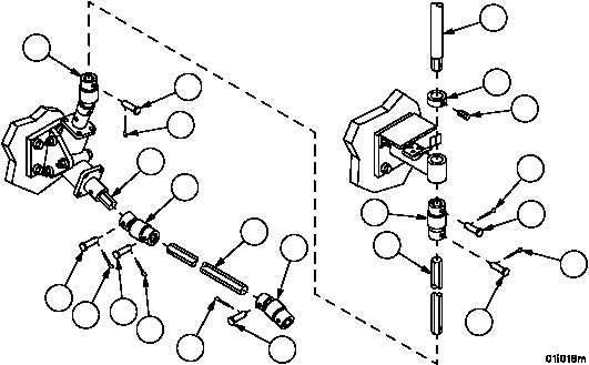
4. Remove cotter pin (8), straight headed pin (9) and universal joint (3) from straight shaft (10). Discard cotter pin.
5. Remove cotter pin (11), straight headed pin (12) and straight shaft (10) from universal joint (13). Discard cotter
pin.
6. Remove cotter pin (14), straight headed pin (15) and universal joint (13) from coupling shaft (16). Discard cotter
pin.
CAUTION
Shaft collar and upper vertical shaft may be difficult to
remove. Do not use excessive force to try and loosen
parts. Use penetrating oil as necessary to loosen parts.
Failure to comply may result in equipment damage.
7. Remove cotter pin (17) and straight headed pin (18) from universal joint (19). Discard cotter pin.
8. Loosen set screw (20) on shaft collar (21) and remove upper vertical shaft (22) and collar (21) while holding uni-
versal joint (19).
9. Remove cotter pin (23), straight headed pin (24) and universal joint (19) from lower vertical shaft (25). Discard
cotter pin.
10. Remove cotter pin (26), straight headed pin (27) and lower vertical shaft (25) from universal joint (28). Discard
cotter pin.
Figure 3
8
9
3
10
11
12
13
14
15
16
17
18
19
20
21
22
23
24
25
26
27
28


