TM 9--2350--292--20--1
0216 00--3
MANUAL FUEL SHUT--OFF CONTROL ASSEMBLY REPLACEMENT --
CONTINUED
0216 00
Installation
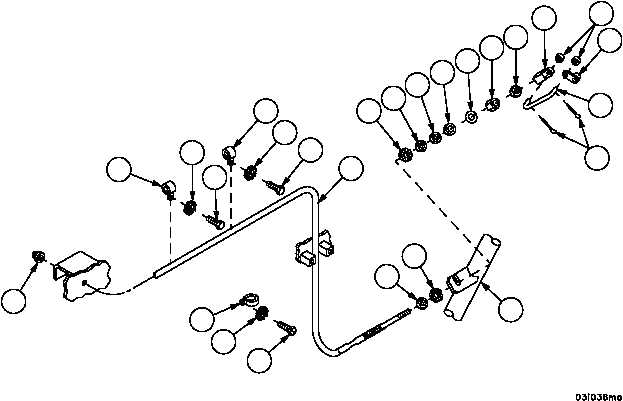
1. Apply adhesive to new grommet (30). Install grommet (30) in bulkhead.
2. Pull control assembly (3) through bulkhead and grommet (30).
3. Secure control assembly (3) to hull with three loop clamps (29), two new lockwashers (27), new lockwasher (28)
and three screws (26).
4. Install nut (25) and new lockwasher (24) on control assembly (3).
NOTE
Make sure connecting link aligns with hole in fuel shut--off
lever before securing control assembly to engine guide.
5. Install control assembly (3) on engine guide (23), then install new lockwasher (22), two nuts (21), flat washer (20),
new preformed packing (19) and nut (18).
6. Install nut (17) and connector (15) on control assembly (3). Tighten nut (17) against connector (15).
7. Install connecting link (14) in connector (15) and shut--off lever (16).
8. Install two flat washers (13) and two new cotter pins (12) in connecting link (14).
Figure 27
12
13
16
17
14
19
20
21
24
25
22
3
15
18
21
26
27
29
29
27
26
29
28
26
30
23


