TM 9--2350--292--20--1
0216 00--4
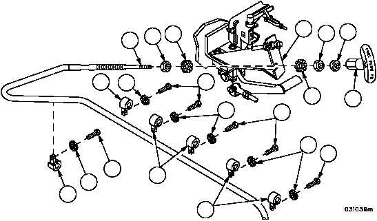
MANUAL FUEL SHUT--OFF CONTROL ASSEMBLY REPLACEMENT --
CONTINUED
0216 00
Installation--Continued
9. Secure control assembly (3) to hull with six loop clamps (11), six new lockwashers (10) and six screws (9).
10. Install nut (8) and new lockwasher (7) on control assembly (3).
11. Install control assembly (3) on bracket (6) with new lockwasher (5) and nut (4).
12. Install nut (1) and handle assembly (2) on control assembly (3). Tighten nut (1) against handle assembly (2).
13. Pull out handle assembly (2) to full shut--off position and adjust control assembly (3) until fuel shut--off level on
engine has rotated to its full downward position (shut--off). Tighten nuts (21 and 25) against engine guide (23) to
secure control assembly (3).
14. Start engine (TM 9--2350--292--10) and test manual fuel shut--off to insure proper adjustment.
Figure 27
1
2
4
5
3
11
10
9
7
8
11
10
9
11
11
9
10
10
6
9
NOTE
FOLLOW--ON MAINTENANCE:
Install engine deck assembly (WP 0417 00)
Close left side engine deck access door
(TM 9--2350--292--10)
Install left side engine air cleaner assembly
(WP 0208 00)
Install gauge panel (WP 0243 00)
END OF TASK