TM 9--2350--292--20--1
0226 00--2
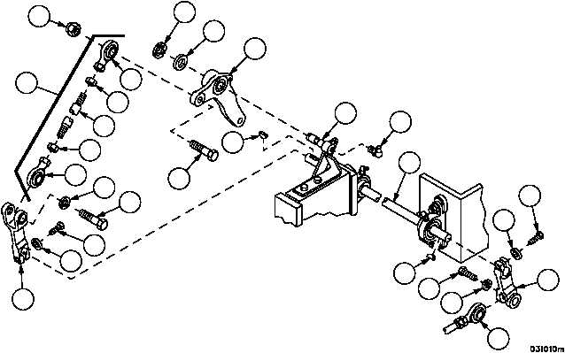
ACCELERATOR CONTROLS AND LINKAGE REPAIR -- CONTINUED
0226 00
Removal--Continued
4. Remove self--locking nut (12), screw (13) and rod assembly (14) from bell crank (7). Discard self--locking nut.
5. Remove screw (15), lockwasher (16) and rod assembly (14) from clevis (17). Discard lockwasher.
6. Remove two rod ends (18 and 19) and two nuts (20) from rod (21).
7. Remove lubrication fitting (22) from bracket assembly (23).
8. Remove retaining ring (24), flat washer (25) and bell crank (7) from bracket assembly (23). Discard retaining ring.
9. Remove screw (26) and lockwasher (27) from clevis (17). Discard lockwasher.
10. Remove clevis (17) and woodruff key (28) from shaft (29).
11. Remove screw (30), lockwasher (31) and rod assembly (32) from lever (33). Discard lockwasher.
12. Remove screw (34) and lockwasher (35) from lever (33). Discard lockwasher.
13. Remove lever (33) and woodruff key (36) from shaft (29).
Figure 35
33
34
35
31
30
36
28
29
22
23
32
12
18
20
21
20
19
16
15
13
17
27
26
14
24
25
7