TM 9--2350--292--20--1
0226 00--10
ACCELERATOR CONTROLS AND LINKAGE REPAIR -- CONTINUED
0226 00
Installation--Continued
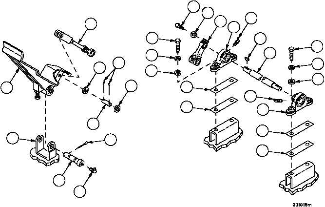
3. Install rod assembly (108) on pedal assembly (123) with pin (126).
4. Install two flat washers (127) and two new cotter pins (125) on pin (126).
5. Install lubrication fitting (120) in pin (121).
6. Apply lubricant to pin (121).
7. Install pedal assembly (123) on floor bracket (124) with pin (121).
8. Install new cotter pin (122) on pin (121).
9. Install two lubrication fittings (119) in two pillow blocks (112).
10. Install two pillow blocks (112) on shaft (94).
11. Install shims (113 and 114) and two pillow blocks (112) using four screws (109), four new lockwashers (110) and
four flat washers (111). Tighten four screws (109) after ensuring alignment of pillow blocks allows easy shaft rota-
tion.
12. Install lever (107) on shaft (94) with woodruff key (117), screw (115) and new lockwasher (116).
Figure 34
94
107
110
111
110
109
111
109
112
114
113
119
112
115116
117
119
108
123
124
125
127
126
127
122
121
120
114
113