TM 9--2350--292--20--1
0230 00--1
HYDRAULIC OIL COOLER AND RELATED PARTS REPAIR
0230 00
THIS WORK PACKAGE COVERS:
Removal, Disassembly, Assembly, Installation
INITIAL SETUP:
Tools and Special Tools
General mechanic’s tool kit
(item 1, WP 0717 00 )
Open--end wrench (item 77, 0717 00)
Suitable container (2.0 gal. min (7.5L))
Materials/Parts
Lockwashers (20) (item 14, WP 0718 00)
Lockwashers (4) (item 52, WP 0718 00)
Gasket (item 203, WP 0718 00)
Preformed packings (2) (item 204, WP 0718 00)
Lockwashers (21) (item 2, WP 0718 00)
Electrical tiedown straps (4) (item 77, WP 0718 00)
Electrical tiedown straps (AR) (item 205, WP 0718 00)
Adhesive (item 25, WP 0716 00)
Sealant (item 37, WP 0716 00)
Safety goggles (item 93, WP 0716 00)
Equipment Conditions
Engine deck assembly removed (WP 0417 00)
Battery power disconnected (WP 0256 00)
Hydraulic system pressure discharged
(WP 0545 00)
NOTE
Perform only those steps necessary to replace the
defective parts.
The procedures for the left and right hydraulic oil cooler
assemblies are similar. The following procedures, except
where noted, are for the right hydraulic oil cooler
assembly.
Removal
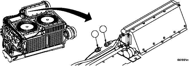
1. Disconnect rotary solenoid wire (1) from wiring harness 3W202 wire 627 connector (2).
Figure 38
1
2