TM 9--2350--292--20--1
0093 00--4
MAIN WINCH FAILS TO RELEASE -- CONTINUED
0093 00
F
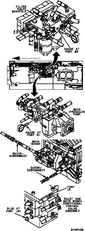
1. Remove gauges from ports PMO and PMI of
hoist and main winch directional control valve
assembly.
2. Install 0--5000 psi dial pressure gauge in filter
valve manifold port MS.
3. Install 0--5000 psi dial pressure gauge with
3/8--inch tee between port X1 of front pump
and attaching hose.
4. Disconnect main winch quick--disconnects at
main winch manifold.
5. Remove plug from port LS of hoist and main
winch directional control valve assembly.
6. Disconnect hose and adapter from port LS1
of hoist and main winch directional control
valve assembly. Install hose and adapter in
port LS and plug port LS1.
7. Start main engine, energize hydraulics, and
set engine speed to 1800 rpm (TM
9--2350--292--10).
8. Place main winch control lever in the payout
position and record gauge readings.
9. Shut down hydraulics and main engine
(TM 9--2350--292--10).
CONTINUED FROM STEP E
no
yes
Go to WP 0091 00
Step E.
WARNING
yes
no
Replace hoist and main
winch directional
control valve assembly
(WP 0556 00). Verify
fault is corrected.
Notify Direct Support
Maintenance
CONTINUED ON NEXT PAGE
FORWARD
Are both pressure readings 4100--4300 psi?