TM 9--2350--292--20--1
0094 00--3
MAIN WINCH FAILS TO HOLD LOAD -- CONTINUED
0094 00
CONTINUED FROM STEP C
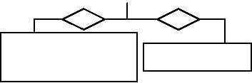
D
Are hoses free of restrictions and damage?
no
yes
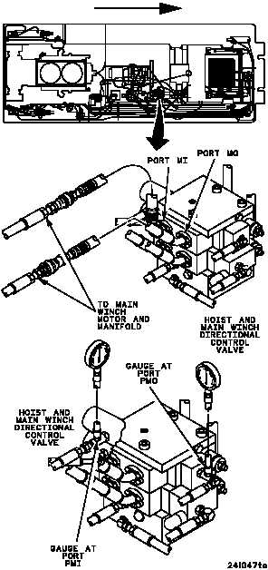
Inspect hoses from hoist and main winch direc-
tional control valve assembly ports MI and MO to
main winch manifold and motor for restrictions
and damage.
Remove restrictions.
If restrictions cannot
be removed, or if there
is damage, replace
(WP 0573 00). Verify
fault is corrected.
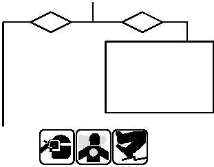
E
Do both gauges read 50 psi or less?
1. Remove gauge from crossport relief valve test port.
2. Install 0--4000 psi testing gauge assembly with
1/4--inch tee between hoist and main winch
directional control valve assembly port PMI and
attaching hose.
3. Install 0--4000 psi testing gauge assembly with
1/4--inch tee between hoist and main winch
directional control valve assembly port PMO and
attaching hose.
4. Start main engine, energize hydraulics, and set
engine speed to 1800 rpm
(TM 9--2350--292--10).
5. With main winch control lever in hold position,
record gauge readings.
6. Shut down hydraulics and main engine
(TM 9--2350--292--10).
yes
no
Notify Direct Support
Maintenance.
Replace hoist and main winch
directional control valve as-
sembly (WP 0556 00). Verify
fault is corrected.
FORWARD
WARNING
CONTINUED ON NEXT PAGE