TM 9--2350--292--20--2
0389 00--5
TORSION BARS AND TORSION BAR ANCHORS REPLACEMENT --
CONTINUED
0389 00
Installation--Continued
CAUTION
Torsion bars installed in left side arm assemblies have an
arrow stamped in solid rubber wheel end of torsion bar
pointing in counterclockwise direction. Torsion bars
installed in right side arm assemblies have an arrow
stamped in solid rubber wheel end of torsion bar pointing
in a clockwise direction. Torsion bars must not be inter-
changed.
NOTE
When installing torsion bars it is not necessary to drive
torsion bars into torsion bar anchors. When torsion bars
are properly aligned, torsion bars will slide easily into tor-
sion bar anchors.
Torsion bars must not be interchanged. Each torsion bar
is stamped (on the outside face) with a part number and
arrow showing the direction of loading torque. Before
installing a new torsion bar be certain that the correct bar
is being installed.
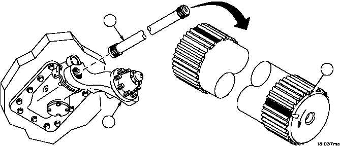
5. Coat splines on both ends of torsion bar (6) and splines on arm assembly (5) with lubricant.
6. Install torsion bar adapter in tapped hole in outside end of torsion bar (6) and attach slide puller to torsion bar
adapter.
7. Position torsion bar (6) so that V--notch (14) cut in chamfer on outer end of torsion bar (6) is on top side (12
o’clock).
Figure 178
6
5
14