TM 9--2350--292--20--2
0391 00--1
TRACK SUPPORT ROLLER REPAIR
0391 00
THIS WORK PACKAGE COVERS:
Removal, Disassembly, Assembly, Installation
INITIAL SETUP:
Tools and Special Tools
General mechanic’s tool kit (item 1, WP 0717 00)
Face wrench socket (item 3, WP 0717 00)
Torque wrench (item 2, WP 0717 00)
Torque wrench (item 9, WP 0717 00)
Seal inserter set (item 8, WP 0717 00)
Track support roller wheel hub inner bearing cup
remover/replacer (item 5, WP 0717 00)
Bearing inserter set (item 7, WP 0717 00)
Remover/replacer handle (item 4, WP 0717 00)
Manual control handle (item 6, WP 0717 00)
Hydraulic jack (item 10, WP 0717 00)
Dial indicator (item 48, WP 0717 00)
Socket wrench adapter (item 86, WP 0717 00)
Materials/Parts
Cotter pin (item 5, WP 0718 00)
Gaskets (2) (item 6, WP 0718 00)
Flat washer (item 7, WP 0718 00)
Sealing compound (item 42, WP 0716 00)
Materials/Parts--Continued
Lockwashers (6) (item 2, WP 0718 00)
Lockwashers (4) (item 8, WP 0718 00)
Seal, plain encased (item 3, WP 0718 00)
Seal, plain encased (item 4, WP 0718 00)
Lubricant (item 3, WP 0716 00)
Hardwood lumber (item 4, WP 0716 00)
Equipment Conditions
Track tension released (TM 9--2350--292--10)
Three track shoe guides removed (WP 0398 00)
Personnel Required
Two
References
TM 9--2350--292--10
NOTE
Perform Removal steps 1 and 3 through 12 and Disas-
sembly step 5 and Installation steps 1 through 12 and 14
through 19 for maintenance of the left front track support
roller.
Perform Removal steps 1, 2, 5, 6, and 8 through 12 and
Disassembly step 5 and Installation steps 1 through 10,
13 and 15 through 19 for maintenance of all track support
rollers except the left front.
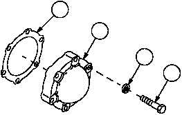
Removal
1. Remove six screws (1), six lockwashers (2), hubcap (3) and gasket (4). Discard lockwashers and gasket.
Figure 182
4
3
2
1
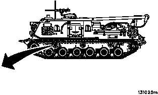
ARMOR SKIRTS
REMOVED FOR CLARITY