TM 9--2350--292--20--2
0398 00--4
TRACK SHOE ASSEMBLY REPLACEMENT -- CONTINUED
0398 00
Installation
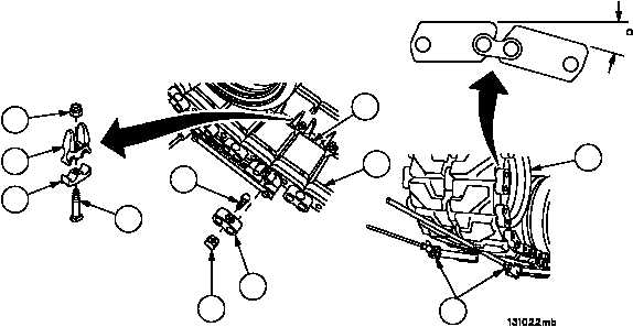
1. Connect one end of new track shoe assembly (1) to track assembly (11) with two end connectors (6), two new
externally released bolts (4) and two new metal wedges (5).
2. Install center guide (15) and cap (14) on new track shoe assembly (1) with screw (13) and new self--locking nut
(12). Torque self--locking nut (12) to 20 lb--ft (27 NSm).
NOTE
It may be necessary to lift end of track assembly to install
track connecting fixtures.
3. Install two track connecting fixtures (8) on track shoe assembly (1) pins and other end of track assembly (11).
4. Tighten two track connecting fixtures (8) until two end connectors (6) can be installed on track shoe assembly (1)
pins.
5. Install two end connectors (6), two new externally released bolts (4) and two new metal wedges (5) on track shoe
assembly pins (1).
6. Remove two track connecting fixtures (8) from track shoe assembly (1) pins.
7. Apply pressure to four end connectors (6) until end connector (6) contacts the ends of new track shoe assembly
(1) pins.
8. Install remaining center guide (15) and cap (14) on track shoe assembly (1) with screw (13) and new self--locking
nut (12). Torque self--locking nut (12) to 20 lb--ft (27 NSm).
9. Remove track binder (TM 9--2350--292--10).
10. Move vehicle (TM 9--2350--292--10), so that new track shoe assembly (1) is just starting over idler wheel (2)
(angle between track shoes should be approximately 16--degrees).
11. Torque four new externally released bolts (4) to 180--200 lb--ft (244--271 NSm).
Figure 188
4
5
6
8
1
16
12
15
14
13
11
2