TM 9--2350--292--20--2
0399 00--3
TRACK ASSEMBLY REPLACEMENT -- CONTINUED
0399 00
Installation--Continued
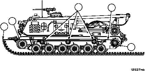
9. Tie fibrous rope (6) to center of track assembly (1), guide fibrous rope (6) over idler wheel (7) and through center
guide grooves on track support rollers (8) to drive sprocket (3).
10. Raise front of track assembly (1) as high as possible.
11. Keep fibrous rope (6) taut, wrap two turns around drive sprocket (3) (clockwise for left track assembly and coun-
terclockwise for right track assembly), over and around top tooth on drive sprocket (3).
NOTE
Turn steering wheel to right if installing left track assem-
bly, turn steering to left if installing right track Assembly
12. With engine at idle, shift transmission to reverse and release brakes (TM 9--2350--292--10).
13. Holding free end of fibrous rope (6) taut, stand to side of drive sprocket (3). This setup forms a power pulley sys-
tem which pulls front of track assembly (1) onto idler wheel (7).
14. When track assembly (1) starts over idler wheel (7) move slowly backward keeping fibrous rope (6) taut around
drive sprocket (3).
1
3
ARMOR SKIRTS REMOVED FOR CLARITY
7
8
6


