TM 9--2350--292--20--2
0407 00--7
SHIFTING CONTROL LINKAGE (ENGINE COMPARTMENT) REPAIR --
CONTINUED
0407 00
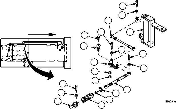
Installation--Continued
14. Connect stud assembly (13) to bell crank (20) with screw (18) and new lockwasher (19).
15. Install bell crank (10) to vehicle hull with bolt (14), new lockwasher (15) and flat washer (16).
16. Install lubrication fitting (17) in bolt (14).
17. Connect stud assembly (13) to bell crank (10) with screw (11) and new lockwasher (12).
18. Install bushing (7), bellows (6) and clamp (5) on threaded rod assembly (3).
19. Apply adhesive to bulkhead--end of bellows (6) and push end of bellows (6) into bulkhead.
20. Connect threaded rod assembly (3) to bell crank (10) with screw (8) and new lockwasher (9).
21. Connect threaded rod assembly (3) to connecting link assembly (4) with screw (1) and new lockwasher (2).
22. Measure 4.5 inches (114.3 mm) back from bulkhead and cement bushing (7) to threaded rod assembly (3).
23. Secure bellows (6) to threaded rod assembly (3) with clamp (5).
Figure 193
1
2
3
4
5
6
7
8
9
10
11
12
13
14
15
16
17
18
19
20
FORWARD