TM 9--2350--292--20--2
0408 00--1
SHIFTING CONTROL LINKAGES ADJUSTMENT
0408 00
THIS WORK PACKAGE COVERS:
Adjustment
INITIAL SETUP:
Tools and Special Tools
General mechanic’s tool kit (item 1, WP 0717 00)
Materials/Parts
Cotter pin (item 19, WP 0718 00)
Lockwashers (6) (item 2, WP 0718 00)
Welding electrodes (AR) (item 9, WP 0716 00)
Equipment Conditions
Storage rack assembly and rocket launcher bracket
removed (WP 0463 00)
Vehicular tool box rack, oddment tray assembly and
bracket removed (WP 0480 00)
Left side air cleaner assembly removed (WP 0208 00)
Left side air cleaner intake hoses and tubes removed
(WP 0212 00)
Subfloor plates #19 and #24 removed (WP 0454 00)
Engine deck assembly removed (WP 0417 00)
Personnel Required
Two
References
TM 9--2350--292--10
Adjustment
NOTE
All adjustments to shifting linkage must finish with the
shift remote control lever on transmission in neutral posi-
tion (pointer on the transmission remote control lever
pointing to center mark) and shift control assembly in
neutral.
All levers, bell cranks and brackets are provided with a
1/8--in. alignment hole to aid in proper alignment during
installation and adjustment. All levers, bell cranks and
brackets must be pinned before being disconnected.
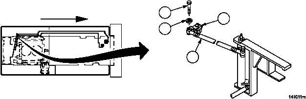
1. Remove screw (1) and lockwasher (2), disconnect threaded rod assembly (3) from transmission remote control
lever (4). Discard lockwasher.
Figure 194
FORWARD
1
2
3
4