TM 9--2350--292--20--2
0408 00--4
SHIFTING CONTROL LINKAGES ADJUSTMENT -- CONTINUED
0408 00
Adjustment--Continued
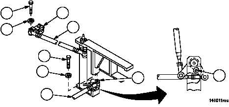
16. Remove screw (28) and lockwasher (29), disconnect connecting link assembly (30) from bell crank (31). Discard
lockwasher.
17. Insert welding electrode (32) in bell crank (31), adjust connecting link assembly (30) until connecting link assem-
bly (30) can be connected to bell crank (31).
18. Connect connecting link assembly (30) to bell crank (31) with screw (28) and new lockwasher (29).
19. Adjust threaded rod assembly (3) until threaded rod assembly (3) aligns with remote control lever (4).
NOTE
Remote control lever at transmission must be in the neu-
tral position (center mark on transmission ) and shift con-
trol assembly must be in neutral, before completing next
step.
20. Connect threaded rod assembly (3) to remote control lever assembly (4) with screw (1) and new lockwasher (2).
21. Adjust steering control lock and neutral safety switch (WP 0358 00 or WP 0359 00).
Figure 194
32
30
1
2
3
4
28
29
31
NOTE
FOLLOW--ON MAINTENANCE:
Install engine deck assembly (WP 0417 00)
Install subfloor plates #19 and #24 (WP 0454 00)
Install left side air cleaner intake hoses and tubes
(WP 0212 00)
Install left side air cleaner assembly (WP 0208 00)
Install vehicular tool box rack, oddment tray assembly
and bracket (WP 0480 00)
Install storage rack assembly and rocket launcher
bracket (WP 0463 00)
END OF TASK