TM 9--2350--292--20--2
0444 00--3
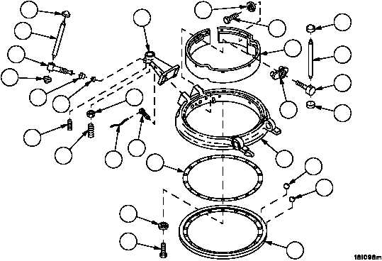
COMMANDER’S CUPOLA REPAIR -- CONTINUED
0444 00
Disassembly
WARNING
1. Remove nonelectrical wire (7), four screws (8) and support (9) from ring assembly (10). Discard nonelectrical
wire.
NOTE
Before buttons can be removed in steps 2 and 3, peened
surfaces must be removed from handle ends with file or
grinder.
2. Remove setscrews (11 and 12), nut (13), block (14), reducer (15), screw (16), pin (17) and two buttons (18) from
support (9).
3. Remove screw (19), pin (20) and two buttons (21) from shoe (22).
4. Remove eight screws (23), eight lockwashers (24) and pad (25) from ring assembly (10). Discard lockwashers.
5. Place ring assembly (10) top side facing down on flat surface.
6. Remove 17 screws (26), 17 lockwashers (27) and retainer (28) from ring assembly (10). Discard lockwashers.
7. Remove 90 bearings (29) and 90 bearings (30) from ring assembly (10).
8. Remove shim (31) from ring assembly (10).
Figure 222
9
10
11
12
13
14
15
16
17
18
18
19
20
21
21
22
23
24
25
26
27
28
29
30
31
8
7