TM 9--2350--292--20--2
0499 00--4
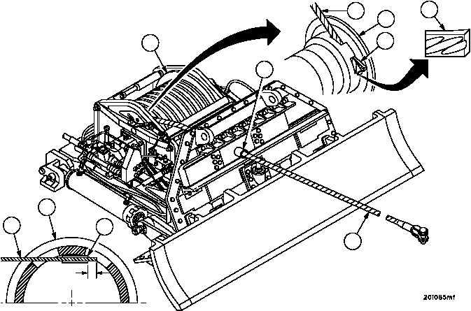
MAIN WINCH WIRE ROPE ASSEMBLY REPLACEMENT -- CONTINUED
0499 00
Installation -- Continued
CAUTION
Failure to align spiral grooves on wedge with correspond-
ing strands of wire rope could prevent proper seating of
wedge in drum pocket. Improper seating may damage
wedge screws and/or cause the wire rope to become
loose.
NOTE
During alignment, the wire rope may need to be rotated
by a crewmember stationed outside the vehicle.
4. Insert wedge (6) in hole of drum (1) next to wire rope (7) approximately 2.0 inches (50.8 mm), aligning the spiral
grooves on wedge (6) with corresponding strands of wire rope (7). Leave approximately 1.0 inch (25.4mm) of
wire rope (7) beyond end of wedge (6).
5. Guide wedge (6) and wire rope (7) into hole of drum (1) approximately 4.0 inches (101.6 mm) by having a crew
member pull wire rope (7) through trumpet (8).
1
7
7
6
1
8
6
1
7
6
1.0”
(25.4 mm)