TM 9--2350--292--20--2
0505 00--2
MAIN WINCH DRUM AND DIAMOND SCREW SYNCHRONIZATION
ADJUSTMENT -- CONTINUED
0505 00
Adjustment--Continued
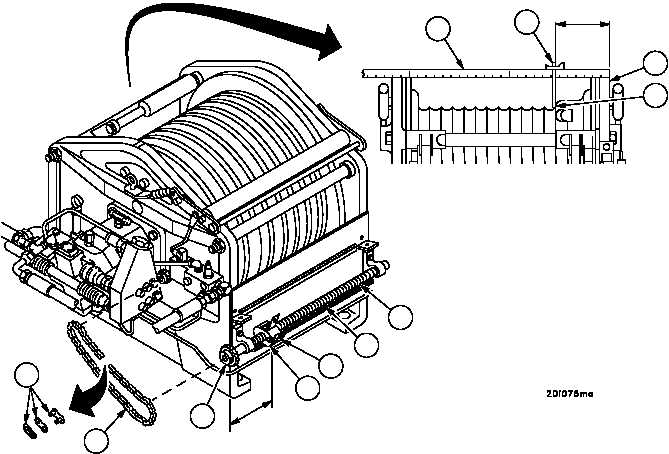
2. Using a steel rule (5) and combination square (6), measure at top of winch, the distance from outside of motor
end winch housing (4) to offset in drum (7). Offset occurs at beginning of rope grooves.
3. Subtract 1.75 inches (44.45 mm) from distance determined in step 2.
4. Check that follower nut (8) is moving away from motor end of winch housing (4) and follower nut trailing edge (9)
is located at distance determined in step 3 (measurement is taken from outside edge of motor end of winch hous-
ing).
NOTE
If measurement in step 4 is not correct, perform steps 5
through 7.
Place rag under roller chain so master link doesn’t drop
down under main winch where it cannot be retrieved.
5. Remove master link (10) in roller chain (11) and remove roller chain.
6. Rotate diamond screw sprocket (12) counterclockwise, when viewed from drive sprocket end (motor end), until
trailing edge of follower nut (9) is at distance determined in step 3.
7. Check that follower nut (8) is riding in groove on the lower edge of nut guard (13) and space between diamond
screw (14) and nut guard (13) is even throughout its full range of travel.
Figure 262
STEP 3
5
6
4
7
10
11
8
13
14
12
9
STEP 4


