TM 9--2350--292--20--2
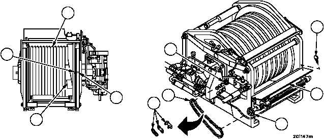
MAIN WINCH AND CABLE GUIDE SYNCHRONIZATION ADJUSTMENT --
CONTINUED
0506 00
Adjustment--Continued
8. Rotate drum (13) until cable pocket (14) is in horizontal (top) position and timing marks on drum flange (1) and
motor end winch housing (2) align.
NOTE
Place rag under roller chain so master link does not drop
down under main winch where it cannot be retrieved.
9. Install roller chain (15) on sprockets (16 and 17). Rotate sprocket (16) the minimum amount possible to achieve
chain (15) assembly. Maximum movement allowed is less than one tooth. Install master link (18).
NOTE
If main winch, upper plate guide or cable guide is re-
moved, replaced or repaired repeat steps 1 through 6.
10. Remove main winch ground hop kit (WP 0498 00).
11. Close nutguard (19) cover and secure with two thumbscrews (20).
Figure 262
1
2
13
14
18
15
20
19
17
16
NOTE
FOLLOW--ON MAINTENANCE:
Install level winder guard (WP 0507 00)
Install main winch wire rope assembly (WP 0499 00)
END OF TASK
0506 00--3/4 blank