TM 9--2350--292--20--2
0506 00--2
MAIN WINCH AND CABLE GUIDE SYNCHRONIZATION ADJUSTMENT --
CONTINUED
0506 00
Adjustment--Continued
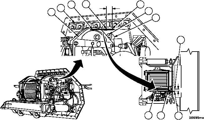
4. Place steel rule (7) flush against motor end housing (5) so that end touches upper plate guide (8), transfer a tem-
porary mark (9) to upper plate guide at point of contact coinciding with outside edge of the (motor end) winch
housing (5).
5. Starting at mark (9) on upper plate guide (8) measure across face of guide using distance determined in step 3.
Scribe a timing mark (10).
6. Check alignment of upper plate guide timing mark (10) and cable guide timing mark (11) on cable guide (12). If
marks are not precisely aligned, measure the amount of misalignment.
a. If misalignment is less than or equal to 0.125 inch (3.17 mm), alignment is within acceptable limits.
Proceed to step 10.
b. If misalignment is greater than 0.125 inch (3.17 mm), proceed to step 7.
7. Rotate main winch drum until upper plate guide timing mark (10) and cable guide timing mark (11) are aligned.
Figure 270
STEP 5
STEP 5
5
8
7
10
9
11
12
10
5
7
9