TM 9--2350--292--20--2
ROLLER BRACKET ASSEMBLY REPAIR -- CONTINUED
0508 00
Installation
NOTE
Do not tighten roller bracket assembly hardware until step
3 is completed.
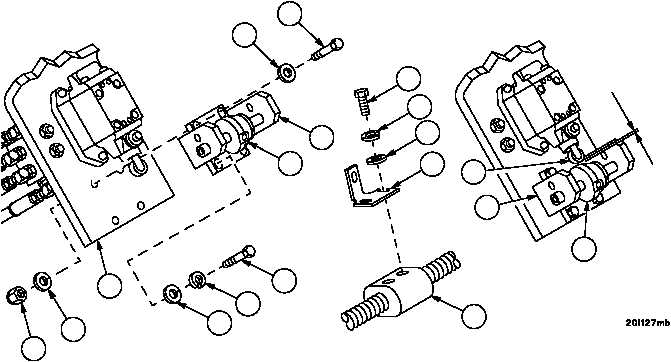
1. Install roller bracket assembly (15) on mounting bracket (16) with screw (13), flat washer (14), flat washer (12)
and new self--locking nut (11).
2. Install three screws (8), three new lockwashers (9) and three flat washers (10) in roller bracket assembly (15).
3. Adjust position of roller bracket assembly (15) so that there is 0.039--0.045 inch (0.991--1.143 mm) gap between
the control valve plunger roller (21) and roller guide (3) when plunger is fully depressed. Tighten four screws (13
and 8) securing roller bracket assembly (15).
4. Install plate (2) on diamond screw (7) with two screws (4), two new lockwashers (5) and two flat washers (6).
5. Install level winder limit switches (WP 0251 00).
Figure 269
2
3
4
5
6
8
9
3
7
0.039--0.045
(0.991--1.143mm
10
11
15
21
15
16
12
13
14
END OF TASK
0508 00--3/4 blank

