TM 9--2350--292--20--2
0519 00--2
HYDRAULIC CONTROL VALVE MANIFOLD SHIELDS AND SPADE CONTROL
VALVE ROD AND HANDLE REPLACEMENT -- CONTINUED
0519 00
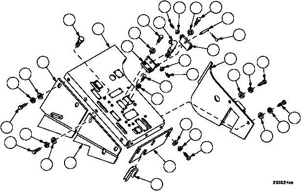
Removal--Continued
NOTE
Note location of studs during disassembly to aid during
assembly. Studs are different size.
3. Remove two cotter pins (9), pin (10) and connector (8). Discard cotter pins.
4. Remove two screws (11) and two nuts (12) from two brackets (13).
5. Remove four screws (14), four lockwashers (15) and two brackets (13). Discard lockwashers.
6. Remove two screws (16), two lockwashers (17), two flat washers (18) and plate (19). Discard lockwashers.
7. Remove two screws (20), two lockwashers (21), two flat washers (22) and plate (23). Discard lockwashers.
8. Remove two screws (24), two lockwashers (25), two flat washers (26) and plate (27). Discard lockwashers.
9. Remove grommet (28) from plate (29). Discard grommet.
10. Remove three screws (30), three lockwashers (31), three flat washers (32) and plate (29). Discard lockwashers.
11. Remove six screws (33), four lockwashers (34) and plate (35). Discard lockwashers.
Figure 275
16
33
35
19
18
17
20
21
22
23
13
15
14
8
12
14
10
9
13
12
11
33
34
25
24
24
11
15
27
32
31
30
29
25
26
26
28