TM 9--2350--292--20--2
0544 00--1
POWER TAKE--OFF (PTO) SHAFT REPLACEMENT
0544 00
THIS WORK PACKAGE COVERS:
Removal, Installation
INITIAL SETUP:
Tools and Special Tools
General mechanic’s tool kit (item 1, WP 0717 00)
Torque wrench (item 2, WP 0717 00)
Wire--twister pliers (item 67, WP 0717 00)
Materials/Parts
Nonelectrical wire (item 40, WP 0716 00)
Lockwashers (8) (item 10, WP 0718 00)
Gasket (item 254, WP 0718 00)
Equipment Conditions
Engine deck grilles removed (TM 9--2350--292--10)
Powerpack removed (WP 0188 00)
Subfloor plate #25, #26, #27 and support #18
removed (WP 0454 00)
Personnel Required
Two
References
TM 9--2350--292--10
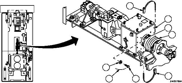
Removal
1. Loosen two clamps (1) and slide boot (2) away from PTO clutch assembly (3).
NOTE
If necessary to turn PTO shaft to access screws, set PTO
clutch assembly manual engagement lever to
DISENGAGED position and manually turn PTO shaft to
desired position.
2. Cut nonelectrical wire (4) and remove from screws (5). Discard nonelectrical wire.
3. Remove four screws (5) and four flat washers (6) from flange (7) mounted to PTO clutch assembly (3).
Figure 292
FORWARD
1
1
2
3
4
5
6
7