TM 9--2350--292--20--2
0545 00--4
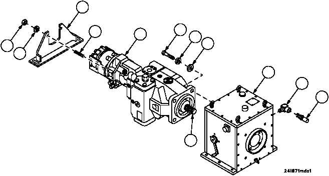
MAIN HYDRAULIC PUMPS’ ASSEMBLY AND POWER TAKEOFF (PTO)
CLUTCH REPLACEMENT -- CONTINUED
0545 00
Installation
1. Apply sealant to threads of adapter (18) and install adapter in PTO clutch assembly (7).
2. Install high temperature switch (17) in adapter (18).
3. Apply lubricant to threads of two studs (14).
4. Install hydraulic pumps’ assembly mount (6) on main hydraulic pumps’ assembly (12) with two studs (14), two
nuts (15) and two flat washers (16). Do not tighten studs (14).
CAUTION
To avoid equipment damage, make sure main hydraulic
pump assembly is kept level and aligned to PTO clutch.
5. Hand tighten two studs (14) until studs bottom out, then back two studs (14) out 0.25 to 2.5 turns.
6. Torque two nuts (15) 28--32 lb--ft (38--43.4 NSm).
7. Align main hydraulic pumps’ assembly splined shaft (13) to internal splines in PTO clutch assembly (7). Slide
main hydraulic pumps’ assembly splined shaft (13) into PTO clutch assembly (7) to engage main hydraulic
pumps’ assembly splined shaft (13) with internal splines of PTO clutch assembly (7).
8. Secure main hydraulic pumps’ assembly (12) to PTO clutch assembly (7) with four screws (9), four new lock-
washers (10) and four flat washers (11). Torque screws to 180--190 lb--ft (244--258 NSm).
14
15
6
12
9
10
11
13
7
17
16
18