TM 9--2350--292--20--2
0549 00--1
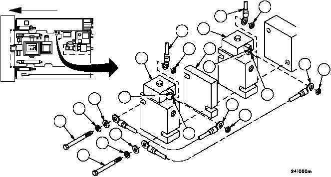
MAIN WINCH SAFETY VALVES REPLACEMENT
0549 00
THIS WORK PACKAGE COVERS:
Removal, Installation
INITIAL SETUP:
Tools and Special Tools
General mechanic’s tool kit (item 1, WP 0717 00)
Materials/Parts
Lockwashers (2) (item 9, WP 0718 00)
Marker tags (item 49, WP 0716 00)
Equipment Conditions
Vehicle MASTER switch OFF (TM 9--2350--292--10)
Hydraulic lines and fittings removed from main winch
safety valves (WP 0567 00)
Subfloor plate #18 removed (WP 0454 00)
References
TM 9--2350--292--10
Removal
NOTE
Tag all electrical connections and electrical leads prior to
removal to aid in installation.
1. Remove two locknuts (1) and two wiring harness 2W601 wires 359B (2) from two threaded rods (3). Retain hard-
ware to aid in installation.
2. Remove two locknuts (4) and two ground leads (5) from threaded rods (6). Retain hardware to aid in installation.
3. Remove two screws (7), two lockwashers (8), two flat washers (9), two ground leads (5), two main winch safety
valves (10) and spacer (11) from vehicle hull. Discard lockwashers.
4. Inspect parts for damage and replace as required.
Figure 298
FORWARD
8
8
2
2
1
1
3
3
10
5
10
4
5
4
7
9
7
9
6
6
11