TM 9--2350--292--20--2
0556 00--1
MAIN/HOIST WINCH DIRECTIONAL CONTROL VALVE ASSEMBLY
REPLACEMENT.
0556 00
THIS WORK PACKAGE COVERS:
Removal, Installation
INITIAL SETUP:
Tools and Special Tools
General mechanic’s tool kit (item 1, WP 0717 00)
Suitable lifting device (350 lbs (158.9 kg) min cap)
Lifting slings (2) (item 25, WP 0717 00)
Materials/Parts
Lockwashers (8) (item 12, WP 0718 00)
Equipment Conditions
Hydraulic hoses and fittings removed from control
valve assembly (WP 0577 00)
Subfloor plates support removed (WP 0454 00)
Commander’s cupola removed (WP 0444 00)
Main winch power reduction manifold removed
(WP 0557 00) (for vehicle equipped with main winch
power reduction manifold)
Personnel Required
Two
References
TM 9--2350--292--10
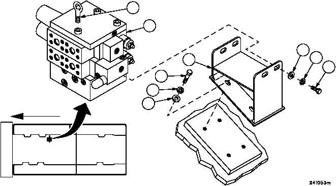
Removal
1. Remove four screws (1), four lockwashers (2) and four flat washers (3). Discard lockwashers.
2. Attach lifting sling to lifting eye (4) and suitable lifting device, remove directional control valve (DCV) assembly (5)
from bracket (6).
3. Remove four screws (7), four lockwashers (8), four flat washers (9) and bracket (6) from hull. Discard lockwash-
ers.
4. Inspect parts for damage and replace as required.
Figure 302
3
2
1
FORWARD
5
6
7
8
9
4