TM 9--2350--292--20--2
0557 00--1
MAIN WINCH POWER REDUCTION MANIFOLD ASSEMBLY AND BRACKETS
REPLACEMENT
0557 00
THIS WORK PACKAGE COVERS:
Removal, Installation
INITIAL SETUP:
Tools and Special Tools
General mechanic’s tool kit (item 1, WP 0717 00)
Suitable lifting device (350 lbs (158.9 kg) min cap)
Lifting slings (2) (item 25, WP 0717 00)
Materials/Parts
Lockwashers (3) (item 13, WP 0718 00)
Lockwashers (4) (item 2, WP 0718 00)
Lockwasher (item 35, WP 0718 00)
Equipment Conditions
Subfloor plates support removed (WP 0454 00)
Hydraulic hoses and fittings removed from main winch
power reduction manifold assembly (WP 0574 00)
Wiring harness 2W612 disconnected from main winch
power reduction manifold (WP 0292 01)
Personnel Required
Two
References
TM 9--2350--292--10
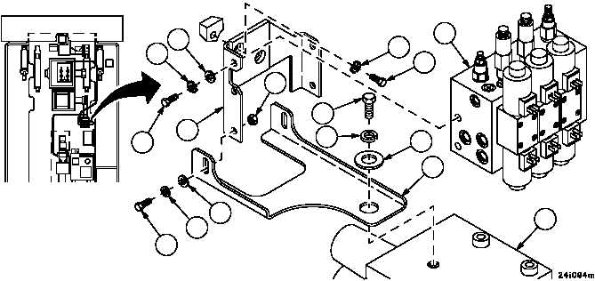
Removal
1. Remove three screws (1), three lockwashers (2), three flat washers (3), and main winch power reduction manifold
(4) from brackets ( and 6). Discard lockwashers.
2. Remove screw (7), lockwasher (8), flat washer (9), and brackets (5 and 6) from directional control valve (DCV)
assembly (10). Discard lockwasher.
3. Remove two screws (11), two lockwashers (12), and brackets (5 and 6) from hull. Discard lockwashers.
4. Remove two nuts (13), two lockwashers (14), two screws (15), two flat washers (16), and separate bracket (5)
from bracket (6). Discard lockwashers.
5. Inspect parts for damage and replace as required.
FORWARD
2
3
4
5
6
7
8
9
10
11
12
13
1
14
15
16