TM 9--2350--292--20--2
0557 00--2
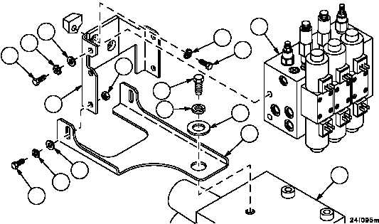
MAIN WINCH POWER REDUCTION MANIFOLD ASSEMBLY AND BRACKETS
REPLACEMENT -- CONTINUED
0557 00
Installation
1. Install bracket (6) on bracket (5) with two screws (15), two flat washers (16), two new lockwashers (14) and two
nuts (13).
2. Install brackets (5 and 6) on hull with two screws (11) and two new lockwashers (12).
3. Install bracket (5) on directional control valve assembly (10) with screws (7), new lockwashers (8) and flat wash-
ers (9).
4. Install main winch power reduction manifold assembly (4) on brackets (5 and 6) with three screws (1), three new
lockwashers (2), and three flat washers (3).
2
3
4
5
6
7
8
9
10
11
12
13
1
14
15
16
NOTE
FOLLOW--ON MAINTENANCE:
Install hydraulic hoses and fittings main winch power
reduction manifold (WP 0574 00)
Connect wiring harness 2W612 to main winch power
reduction manifold (WP 0292 01)
Start engine, operate main winch and hoist winch hy-
draulic controls several times to purge air from hoses
and valve assembly (TM 9--2350--292--10)
Check hydraulic system for leaks, fill reservoir
(TM 9--2350--292--10)
Install subfloor plates support (WP 0454 00)
END OF TASK