TM 9-2350-256-20
12-7 REPLACE HYDRAULIC DRAIN VALVE AND RELATED PARTS
THIS TASK COVERS
a. Removal
b. Installation
INITIAL SET-UP
Tools:
Equipment Conditions:
Tool kit, general mechanic's (Appendix C, item 53)
Rear intermediate right floor plate removed (see
paragraph 9-8)
Parts:
Rear center floor plate removed (see paragraph
Drivescrews (4) (Appendix G, item 12)
9-12)
Lockwashers (4) (Appendix G, item 132)
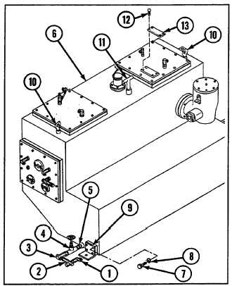
a. REMOVAL
1 Remove elbow (1) and tee (2).
2 Remove tee (3), valve (4), and nipple (5) from tank (6).
3 Remove four screws (7) with four lockwashers (8)
and bracket (9).
4 Remove two eyebolts (10).
5 Remove gage rod (11).
6 Remove four drivescrews (12) and plate (13).
b. INSTALLATION
1 Install plate (13) with four new drivescrews (12).
2 Install gage rod (11) and two eyebolts (10).
3 Install bracket (9) with four new lockwashers (8)
and four screws (7).
4 Install nipple (5), valve (4), and tee (3) to tank (6).
5 Install tee (2) with elbow (1).
NOTE
Follow-on maintenance: Install rear center floor plate (see paragraph 9-12)
Install rear intermediate right floor plate (see paragraph 9-8)
12-8 REPLACE HYDRAULIC SUBPLATE ID PLATE
THIS TASK COVERS
a. Removal
b. Installation
INITIAL SET-UP
Tools:
Parts:
Tool kit, general mechanic's (Appendix C, item 53)
Drivescrews (36) (Appendix G, item 13)
Lockwashers (4) (Appendix G, item 129)
12-35