CHAPTER 2: VEHICLE MAINTENANCE INSTRUCTIONS
TM 9-2350-256-20
2-19 ELECTRICAL TROUBLESHOOTING-Continued
RIGGER'S LIGHTS AND FRONT SIGNAL LIGHT-Continued
WARNING
Remove all jewelry such as rings, dog tags,
bracelets, etc. If jewelry contacts a metal
surface a direct short may result in instant
heating of tools, damage to equipment, and
injury or death to personnel.
P
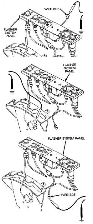
Reconnect wire 325 to flasher side of FLASHER switch.
Disconnect wire 325 of red flasher breaker to switch
wiring harness from circuit breaker side of FLASHER
switch. Place red lead of multimeter in of wire 325 and
black lead to ground. Turn MASTER switch on and
check for voltage. Turn MASTER switch OFF. If
voltage is present, replace FLASHER switch (see
paragraph 6-11). If voltage is not present, go to step Q.
Q
Reconnect wire 325 of red flasher breaker to switch
cable
to
circuit
breaker
side
FLASHER
switch.
Disconnect wire 325 from FLASHER switch side of 15 A
circuit breaker. Place red lead of multimeter on circuit
breaker terminal and black lead to ground. Turn
MASTER switch on and check for voltage. Turn
MASTER
switch
OFF.
If
voltage
is
present,
repair/replace wire 325 of red flasher breaker to switch
wiring harness from 15 A circuit breaker to FLASHER
switch (see paragraph 6-66). If voltage is not present,
go to step R.
R
Reconnect wire 325 of red flasher breaker to switch
wiring harness to switch side of 15 A circuit breaker.
Disconnect wire 325 of switch panel, radio and bilge
pump to bulkhead wiring harness from main switch
panel side of 15 A circuit breaker. Place red lead of
multimeter in wire 325 and black lead to ground. Turn
MASTER switch on and check for voltage. Turn
MASTER switch OFF. If voltage is present, replace 15
A circuit breaker (see paragraph 6-11). If voltage is not
present, reconnect wire 325 of switch panel, radio, and
bilge pump to bulkhead wiring harness to main switch
panel side of 15 A circuit breaker.
2-326