SECTION V: VEHICLE WIRING
TM 9-2350-256-20
9
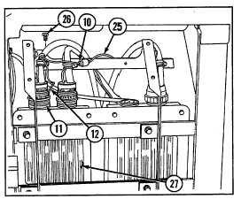
Disconnect connector (11) and lead (12) by
removing screw (26) from APU voltage regulator
(27).
b. DISASSEMBLY
Disassemble wiring harness (see Chapter 6, Section
VII).
c. ASSEMBLY
Assemble wiring harness (see Chapter 6, Section VII).
d. INSTALLATION
1
Connect connector (11) and lead (12) with screw
(26) to APU voltage regulator (27).
2
Connect connector (10) to bulkhead to APU,
master relay, and rigger's lights wiring harness (25).
3
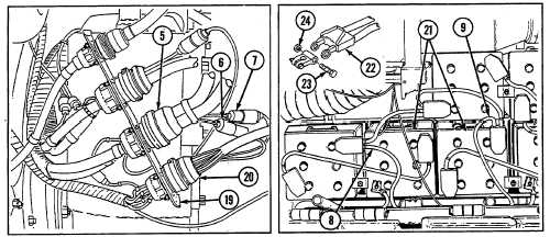
Connect two connectors (8 and 9) to batteries (21) using bolt (23) and nut (24). Push insulator (22) back on
battery terminal.
4 Connect two connectors (6 and 7) to bulkhead to main engine bracket and rear fuel tank transmitter wiring
harness (20).
5
Connect connector (5) to main engine disconnect (19).
6
Connect two leads (3 and 4) to slave receptacle (18) using new lockwasher (21) and screw (19).
7
Connect connector (2) to master relay (17).
8
Connect connector (1) to main engine voltage regulator (16).
9
Install eight clamps (13) using new lockwasher (15) and screw (14) for each.
NOTE
Follow-on maintenance:
Install air inlet doors if removed (see paragraph 9-56)
6-85