TM 9--2350--292--20--1
0116 00--4
STOPLIGHT ASSEMBLIES FAIL TO OPERATE -- CONTINUED
0116 00
CONTINUED ON NEXT PAGE
CONTINUED FROM STEP F
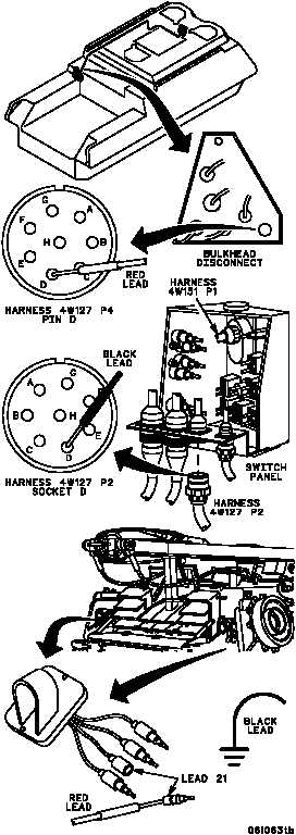
G 1. Reconnect harness 4W151 P1 to light switch.
2. Place one multimeter lead in harness 4W127
P2 socket D and other lead in harness
4W127 P4 pin D. Check for continuity.
Is continuity present?
no
yes
Repair (WP 0290 00) or
replace (WP 0324 00)
harness 4W127. Verify
fault is corrected.
H 1. Reconnect harness 3W142 P1 to bulkhead
disconnect.
2. Reconnect harness 4W105 P1 and 4W127
P2 to switch panel (if disconnected).
3. Remove right side and left side access
covers holding stoplight assemblies.
4. Disconnect lead 21 from right and left
stoplight assemblies below access covers.
5. Turn MASTER switch ON and place light
switch in the SERVICE DRIVE position
(TM 9--2350--292--10).
6. Place multimeter red lead in both lead 21
connectors (one at a time) while holding black
lead to ground. Check for voltage.
7. Turn MASTER switch OFF
(TM 9--2350--292--10).
Is 24 V dc present at both checks?
no
yes
Repair (WP 0290 00) or
replace (WP 0294 00)
harness 3W142. Verify
fault is corrected.
CONTINUED
FROM STEP B