TM 9--2350--292--20--2
0706 00--7
M2A2 GAS PARTICULATE FILTER UNIT (GPFU), HOSE ASSEMBLIES,
FRAME ASSEMBLIES, BRACKETS, LEAD ASSEMBLY 4W303 AND
ASSOCIATED HARDWARE REPLACEMENT -- CONTINUED
0706 00
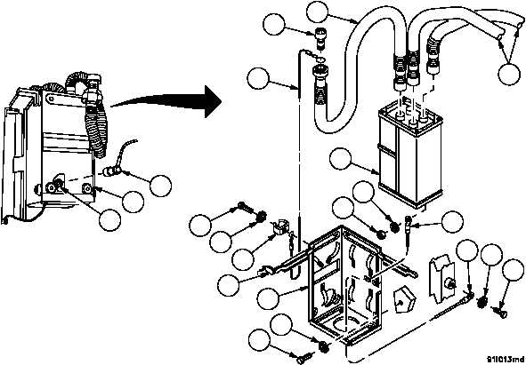
Installation--Continued
NOTE
Make sure screws are tightened sufficiently to cause ex-
ternal tooth lockwasher to cut through paint to make an
electrical contact. Removal of paint and primer at inter-
face mounting surface is acceptable to achieve proper
component ground.
6. Install frame assembly (42) and one end of lead assembly 4W303 (34) in vehicle with five screws (44) and five
new lockwashers (45).
7. Install M2A2 gas particulate filter unit (31) in frame assembly (42) and close catch (43).
8. Install clamp (39) and wire rope assembly (37) on frame assembly (42) with screw (40) and new lockwasher (41).
9. Install wire rope assembly (37) on orifice connector (38), if removed.
10. Connect loose ends of two hose assemblies (35) and one end of hose assembly (36) to manifold on M2A2 gas
particulate unit (31). Secure loose end of hose assembly (36) with orifice connector (38) and wire rope assembly
(37) in clamp (39).
11. Install lead assembly 4W303 (34) on M2A2 gas particulate filter unit (31) with nut (32) and new lockwasher (33).
12. Connect wiring harness 4W306 connector P2 (29) to connector J1 (30) on M2A2 gas particulate filter unit (31).
Figure 374
29
31
30
40
41
39
42
44
45
43
36
35
32
33
34
34
45
44
31
37
38