TM 9--2350--292--20--2
0501 00--1
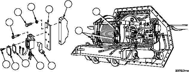
PAYOUT AND LAYER LIMIT SWITCHES REPLACEMENT
0501 00
THIS WORK PACKAGE COVERS:
Removal, Installation
INITIAL SETUP:
Tools and Special Tools
General mechanic’s tool kit
(item 1, WP 0717 00)
Marker tags (item 49, WP 0716 00)
Equipment Conditions
Main winch and spade assembly removed
(WP 0497 00)
NOTE
There are two layer limit switches and one payout limit
switch. All three limit switches are replaced in the same
manner. This task replaces only one limit switch.
Removal
NOTE
Tag all electrical connections and electrical leads prior to
removal to aid in installation.
1. Remove two screws (1), cover plate (2) and gasket (3) from layer limit switch (4).
2. Disconnect connector (5) from bottom of layer limit switch (4).
3. Disconnect wiring harness 2W602 wire 361A or 361B and wire 10 from layer limit switches (4) or wire 375 and
wire 10 from payout limit switch (6).
4. Remove two screws (7) and limit switch (4 or 6).
5. Loosen screw on lever (8), remove lever (8) from limit switch (4 or 6).
6. Remove two screws (9), two flat washers (10) and bracket (11) from main winch (12).
7. Inspect parts for damage and replace as required.
Figure 264
1
2
3
5
8
4
6
12
11
10
9
7