TM 9--2350--292--20--2
0501 00--2
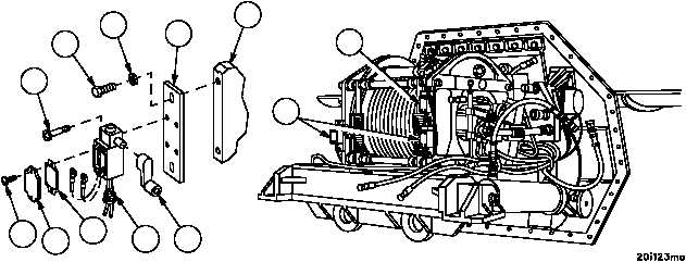
PAYOUT AND LAYER LIMIT SWITCHES REPLACEMENT -- CONTINUED
0501 00
Installation
1. Install bracket (11) on main winch (12) with two screws (9) and two flat washers (10). Do not tighten screws (9).
2. Install lever (8) on limit switch (4 or 6). Do not tighten screw.
3. Install limit switch (4 or 6) with two screws (7).
4. Connect wiring harness 2W602 wire 361A or 361B and wire 10 to layer limit switches (4) or wire 375 and wire 10
to payout limit switch (6).
5. Install gasket (3) and cover plate (2) on layer limit switch (4) with two screws (1).
6. Connect connector (5) to bottom of layer limit switch (4).
7. Adjust layer limit switches (4) (WP 0503 00) and/or payout limit switches (6) (WP 0502 00).
Figure 264
1
2
3
5
8
4
6
12
11
10
9
7
NOTE
FOLLOW--ON MAINTENANCE:
Install main winch and spade assembly (WP 0497 00)
END OF TASK