TM 9--2350--292--20--2
0503 00--2
LAYER LIMIT SWITCHES ADJUSTMENT -- CONTINUED
0503 00
Adjustment--Continued
CAUTION
Clean grease and dirt from upper roller prior to perform-
ing limit switch task adjustment. Failure to comply will
cause inaccurate measurements resulting in damage to
equipment.
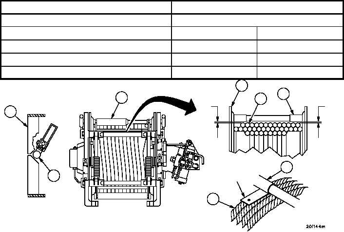
2. Keeping wire rope (1) under tension, pay out at least two wraps from the top layer while observing gap between
upper spring guide bracket (2) and nylon roller (3). When gap is at its minimum distance, note location of wire
rope (1) under the upper roller (4). This is the high spot on the drum.
3. Mark location of high spot found in step 2 with electrical tape on the winch drum flange (5).
4. Pay in wire rope (1) until high spot is directly under upper roller support tube (6).
5. Using go/no--go gauges, measure the clearance distance between the wire rope (1) and the upper roller support
tube (6) at location A for both the right and left side.
6. Find the MEASURED CLEARANCE DISTANCE in the table below and write down the corresponding GAP SET-
TING RANGE that matches the measured clearance distance for both the right and left side.
MEASURED CLEARANCE /GAP SETTING RANGE
MEASURED CLEARANCE DISTANCE
GAP SETTING RANGE
1/8--in. or less
Do not adjust limit switch. Troubleshoot misspooling.
LOW
HIGH
1/8--in. go -- 3/16--in. no--go
0.005
0.025
3/16--in. go -- 1/4--in. no--go
0.036
0.056
1/4--in. or more
0.068
0.088
Figure 264
A
4
2
3
1
6
5
A
6
1
GO/NO--GO
GAUGE


