TM 9--2350--292--20--2
0503 00--5
LAYER LIMIT SWITCHES ADJUSTMENT -- CONTINUED
0503 00
Adjustment--Continued
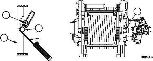
12. Adjust right side layer limit switch (9) for bottom roller position.
a. Verify the right side layer limit switch (9) is not already in the active position by manually moving the
nylon roller (3) until an audible click is heard.
b. If no click is heard then adjust right side layer limit switch (9) by loosening clamp nut (13) and rotating
right layer limit switch (9) actuator arm.
c. Tighten clamp nut (13) and verify the right side layer limit switch (9) is not in the active position by
manually moving the nylon roller (3) until an audible click is heard.
NOTE
More than one feeler gauge may be used together to ob-
tain the required thickness.
d. Using the gap setting range recorded for the right side layer limit switch (9) in step 6, select feeler
gauge(s) that correspond to the LOW gap setting range.
e. Insert feeler gauge(s) between lower spring guide (11) and nylon roller (3). Layer limit switch (9)
should not click.
f. Using the gap setting range recorded for the right side layer limit switch (9) in step 6, select feeler
gauge(s) that correspond to the HIGH gap setting range.
g. Insert feeler gauge(s) between lower spring guide (11) and nylon roller (3). Layer limit switch (9)
should click.
h. If layer limit switch (9) activates when it shouldn’t or doesn’t activate when it should, then loosen
clamp nut (13) and rotate layer limit switch (9) activating arm to a new position.
i. Tighten clamp nut (13) and repeat steps 12d through 12g. When the LOW range feeler gauge(s) do
not activate layer limit switch (9) and the HIGH range feeler gauge(s) do activate layer limit switch (9)
the adjustment is correct.
9
3
11
13
GAUGE


