CRANKSHAFTS & CAM GEARS
Auxiliary Drive with Clutch
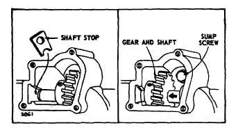
Fig. 28. Auxiliary P.T.O.
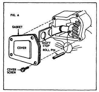
When installing cover, Fig. 29, put non-hardening sealant
on cover screws.
Fig. 29. Installing Cover
AUXILIARY P.T.O. -- With Clutch –
Model Series 110980
This auxiliary power take-off shaft is perpendicular to the
crankshaft. It rotates at the rate of one revolution for
every 8-1/2 revolutions of the crankshaft. Rotation of the
shaft is controlled by a clutch on the cam gear. The
clutch is engaged or disengaged by a control lever
mounted on the oil sump.
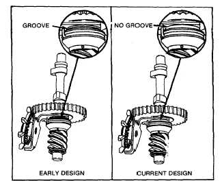
Early production cam gears, Fig. 30, are serviced as an
assembly consisting of cam gear oil slinger, clutch hub,
clutch spring and clutch sleeve assembly. Later
production cam gears are serviced as individual parts
except for the cam gear which consists of cam gear, oil
slinger and clutch hub.
Fig. 30. Cam Gear and Clutch
To remove sump: Sump is held on by six screws. Five
screws are exposed. The sixth screw is under the
auxiliary drive cover, Fig. 28. Remove cover and lift out
shaft stop, Fig. 28. Slide driveshaft and gear over to
expose head of cap screw. Cap screw can be removed
with 7/16" socket.
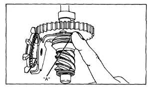
INSPECT CLUTCH OPERATION
Push on spring tang, "A," Fig. 31, turning spring and
clutch sleeve in a counterclockwise direction. Spring and
sleeve should rotate approximately 1/8" turn. Worm gear
should not rotate in the same direction. With clutch
released, worm gear should rotate freely in both
directions.
Fig. 31. Inspect Clutch
CHECK CAM GEAR
Check worm gear end play using feeler gauges at point
"A," Fig. 32. End play should not be less than .004" (.10
mm) or more than .017" (.43mm).
10