TM 5-4240-501-14P
CRANKSHAFTS & CAM GEARS
Auxiliary Drive with Clutch
Fig. 36. - Install Clutch Sleeve
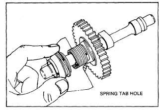
Slide thin thrust washer and worm on cam gear. Slide in
thick thrust washer. Slide on copper washer with gray
coated side toward thrust washer. Install "E" ring and
check worm gear end play as described in "Check Cam
Gear" section, page 10.
Inspect cam gear assembly as outlined in "Inspect Clutch
Operation" section, page 10.
REMOVE CONTROL LEVER SHAFT
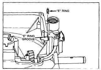
Remove "E" ring, Fig. 37. Slide control lever and shaft
out slowly until lever clears boss on sump. Slowly
release spring tension and then remove shaft, spring and
"O" ring seal.
Inspect shaft assembly for loose lever, worn or broken
parts. Replace as needed.
Fig. 37. - Remove "E" Ring
ASSEMBLE CONTROL LEVER AND
SHAFT ASSEMBLY
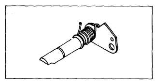
Install return spring on shaft and lever assembly as
shown in Fig. 38. Then install "O" ring seal on shaft.
Lubricate "O" ring and shaft lightly with engine oil.
Fig. 38. - Assemble Spring
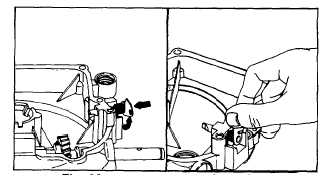
Slide control lever assembly into shaft bore, Fig. 39, as
far as it will go. Rotate lever clockwise to put tension on
return spring. When lever clears stop boss, push lever
and spring in until lever stops. Install "E" ring. Leg of
spring may need to be pushed against sump, Fig. 40.
Lever Installation Spring Installation
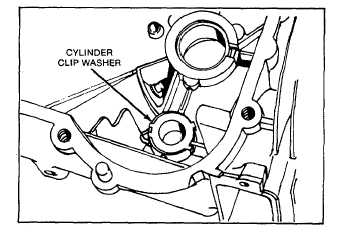
CYLINDER CLIP WASHER
Should clip washer in cylinder require replacing, be sure
flat on clip washer is in line with flat on cam bearing boss
and spring tabs are on both sides of cam bearing web,
Fig. 41.
Fig. 41.—Cylinder Clip Washer
12
Fig. 39.
Fig. 40.