CRANKSHAFTS & CAM GEARS
Auxiliary Drive with Clutch
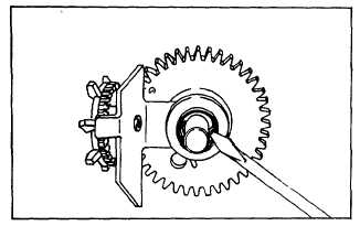
Fig. 32. - Check Cam Gear
CAM GEAR DISASSEMBLY -
EARLY DESIGN
Remove "E" ring retainer. Slide off copper washer, thick
thrust washer, worm and thin thrust washer. Cam gear,
oil slinger, clutch sleeve and springs are serviced with a
current production assembly.
INSPECT PARTS
Inspect for worn, burred or broken parts and replace as
required.
ASSEMBLE CAM GEAR -
EARLY DESIGN
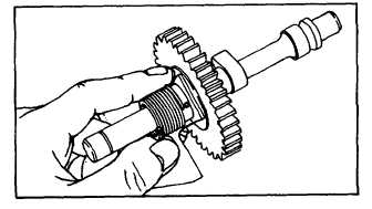
Slide worm gear with thin thrust washer on cam gear.
Slide on thick thrust washer. Slide on copper colored
washer with gray coated side toward thick thrust washer.
Install "E" ring retainer and check worm end play as
described in "Check Cam Gear" section above. Inspect
cam gear assembly as outlined in "Inspect Clutch
Operation" section above.
DISASSEMBLY CAM GEAR -
CURRENT DESIGN
Remove "E" ring. Slide off thrust washers and worm
gear. Use thin blade screwdriver or similar tool to pry
lower clutch spring tab out of hole in clutch sleeve, Fig.
33. Remove clutch sleeve. Slide clutch spring down,
Fig. 34 and lift out upper spring tab to remove spring.
Cam gear, oil slinger and clutch drive hub are serviced
as an assembly.
Fig. 33. - Remove Clutch Sleeve
Fig. 34. - Remove Clutch Spring
INSPECT PARTS
Inspect for worn, broken or burred parts. Replace as
required.
ASSEMBLE CAM GEAR - CURRENT DESIGN
Assemble clutch spring as shown in Fig. 35. Align E
hole in clutch sleeve with tab or spring and slide on.
Depress spring tab,’ if required. When clutch sleeve is in
place, spring tab should be in sleeve hole, Fig. 36.
Fig. 35. - Assemble Clutch Spring
11