CHAPTER 9: MAINTENANCE OF HULL-AND CAB-RELATED COMPONENTS
TM 9-2350-256-20
9-78
REPLACE/REPAIR/SERVICE ACCELERATOR CONTROLS AND LINKAGES-
Continued
29
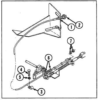
Install throttle control assembly (2) with two nuts
(7).
30
Tighten two self-locking nuts (6).
31
Install clamp (3) with new lockwasher (5) and screw
(4).
32
Tighten self-locking nut (1) on throttle control
assembly (2).
NOTE
Follow-on maintenance:
Only install or close items necessary to gain access to area of linkage
requiring removal.
Install oddment tray (see paragraph 9-104)
Install toolbox rack (see paragraph 9-103)
Install ammunition rack (see paragraph 9-100)
Install air inlet grilles if removed (see paragraph 9-57)
Install air inlet doors if removed (see paragraph 9-56)
Install cab subfloor plates (see paragraphs 9-1 through 9-23)
Install left-side air cleaner (see paragraph 4-24)
Install powerplant (see paragraph 3-1)
9-79
SERVICE ALIGNMENT AND ADJUSTMENT OF ACCELERATOR CONTROLS
AND LINKAGES
THIS TASK COVERS
a. Accelerator Linkage Alignment
b. Adjustment (Full Throttle)
c. Hand Throttle Adjustment
d. Rubber Boot Final Adjustment
INITIAL SET-UP
Tools:
Material:
Equipment Conditions:
Tool kit, general mechanic's
Adhesive, rubber-base
Powerplant removed for alignment
(Appendix C, item 53)
(Appendix D, item 3)
only (see paragraph 3-1)
Punches, drive (2) (locating
Engine throttle lever linkage
pins) (Appendix C, item 37)
disconnected (see paragraph 9-78)
a. ACCELERATOR LINKAGE ALIGNMENT
1
Loosen nuts (1 and 2).
9-182