CHAPTER 9: MAINTENANCE OF HULL-AND CAB-RELATED COMPONENTS
TM 9-2350-256-20
9-80 REPLACE/REPAIR/SERVICE SERVICE BRAKE CONTROLS AND LINKAGES
THIS TASK COVERS
a. Removal
b. Disassembly
c. Assembly
d. Installation
e. Alinement and Adjustment
INITIAL SET-UP
Tools:
Equipment Conditions:
Tool kit, general mechanic's (Appendix C, item 53) NOTE
Pliers, retaining ring, external (Appendix C,
item 31)
Only remove or open items necessary to
Punches, drive (7) (locating pins) (Appendix C,
gain access to area of linkage requiring
item 37)
removal.
Material/Parts:
Powerplant removed (see paragraph 3-1)
Adhesive, rubber-base (Appendix D, item 3)
Left-side air cleaner removed (see
Lockwashers (6) (Appendix G, item 130)
paragraph 4-24)
Lockwashers (3) (Appendix G. item 132)
Cab subfloor plates removed (see paragraph 9-1
Lockwashers (19) (Appendix G, item 134)
through 9-23)
Lockwashers (9) (Appendix G. item. 136)
Air inlet doors removed as necessary (see
Pins, cotter (14) (Appendix G, item 216)
paragraph 9-56)
Pin, spring (Appendix G, item 234)
Air inlet grilles removed as necessary (see
Reference:
paragraph 9-57)
TM 9-2350-256-10
Ammunition rack removed (see paragraph 9-100)
Toolbox rack removed (see paragraph 9-103)
Oddment tray removed (see paragraph 9-104)
a.
REMOVAL
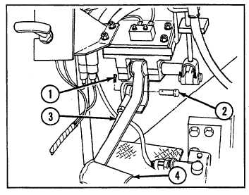
1
Remove cotter pin (1) and straight pin (2), and disconnect rod assembly (3) from brake pedal (4).
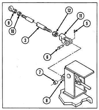
2
Remove cotter pin (5), straight pin (6), bearing (7),
3
Remove rod end (9) and nut (10) from one end of rod
assembly (3) and remove clevis (11) and nut (12) from
other end of rod assembly.
9-184