SECTION V: CONTROLS AND LINKAGES
TM 9-2350-256-20
2
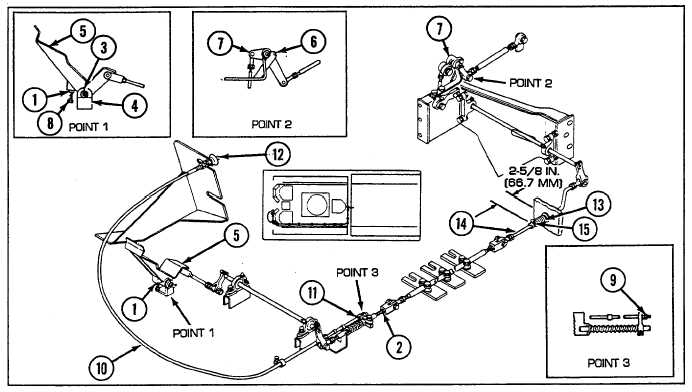
Insert 1/8-in.-(3.2-mm-) diameter locating pin (3) in bracket (4) and accelerator pedal (5) (point 1).
3
Adjust linkage leaving nuts (1 and 2) loose until 1/8-in.-(3.2-mm-) diameter locating pin (6) can be inserted in bell
crank (7) (point 2).
4
Tighten nuts (1 and 2). Remove locating pins (3 and 6) and connect linkage to engine throttle lever (see
paragraph 9-78).
b.
ADJUSTMENT (FULL THROTTLE)
Loosen nut (1) (point 1) and adjust throttle stop (8) as required to obtain full throttle acceleration. Then tighten nut.
c.
HAND THROTTLE ADJUSTMENT
1
Loosen two nuts (9) (point 3) on throttle control cable (10) at accelerator connecting lever (11). Push in throttle
control handle (12) all the way.
2
Adjust two nuts (9) until 3/16-in. (4.8-nmm) movement of throttle control handle (12) causes increase in engine
speed with engine operating at idle.
d.
RUBBER BOOT FINAL ADJUSTMENT
With throttle control handle (12) adjusted and accelerator pedal (5) released, extend rubber boot (13) to 2-5/8 in. (66.7
mm) (as shown in illustration). Cement rubber boot to bulkhead with adhesive and clamp to rod (14) with clamp (15) (see
paragraph 9-78).
NOTE
Follow-on maintenance:
Connect engine throttle lever linkage (see paragraph 9-78)
Install powerplant if removed (see paragraph 3-1)
9-183