SECTION II: INSTALLATION PROCEDURES
TM 9-2350-256-20
1-6 ENGINE GENERATOR COOLING EXHAUST
1
Remove exhaust air elbow from front shroud and exhaust air tube (see paragraph 6-1).
2
Remove right-rear upper engine cover (see paragraph 4-2).
NOTE
Valve assembly (1) should be operated manually to ensure that valve is centered
properly in shroud opening prior to tightening screws (2).
3
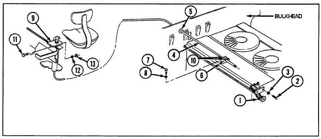
Install kit-furnished valve assembly (1) on right-rear flywheel end, upper shroud assembly with two kit-
furnished screws (2) and two new lockwashers (3).
4
Install right-rear upper engine cover (see paragraph 4-2), previously removed.
5
Remove pipe plug in bulkhead (engine compartment side) to provide opening for control cable (4).
6
Install kit-furnished grommet (5) in bulkhead using rubber adhesive (Table I-I, item 1).
7
Install kit-furnished support (6) with two kit-furnished screws (7) and two new lockwashers (8).
8
Install kit-furnished bracket and control assembly (9) as follows:
NOTE
Care should be taken not to damage rubber seals (10) when removing them from their
retaining ferrules.
a. Remove two rubber seals (10) with nuts from control cable (4). Discard nuts.
b. Route control cable (4) through floor plate support at oddment tray on driver's side, under floor plates,
through bulkhead grommet (5), and through support (6). Place rubber seal (10) on each side of support.
c. Secure bracket and control assembly (9) with screw (11), new lockwasher (12), and nut (13).
I-5


