SECTION II INSTALLATION PROCEDURES
TM 9-2350-256-20
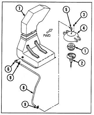
1-9 FUEL TANK VENT
1
Bond kit-furnished seal (1) to existing cap
assembly (2) with adhesive sealant (Table I-1,
item 4).
2
Remove plug (3) from fuel tank filler cover (4).
3
Install kit-furnished elbow (5) in fuel tank filler
cover (4).
4
Install kit-furnished elbow (6) in left engine air
inlet pipe (7).
5
Connect kit-furnished hose (8) between elbows (5
and 6). Secure each end with clamp (9).
6
Seal fuel tank filler cover (4) to mating surface
with caulking compound (Table I-1, item 3).
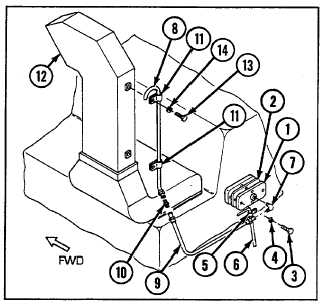
I-10 ACETYLENE VENT
1
Install kit-furnished cover (1) and new gasket (2)
over acetylene vent holes with three kit-furnished
screws (3) and three new lockwashers (4). Apply
adhesive sealant (Table I-1, item 4) to gasket
upon installation.
2
Install kit-furnished loop clamp (5) over fuel tank
vent hose (6) and secure with fourth kit-furnished
screw (3) and new lockwasher (4).
3
Install kit-furnished elbow (7) in cover (1).
4
Connect kit-furnished tube assembly (8) to tube
assembly (9) with kit-furnished union (10).
5
Place two kit-furnished loop clamps (11) over kit-
furnished tube assembly (8).
6
Connect end of tube assembly (9) to kit-furnished
elbow (7).
7
Secure kit-furnished tube assembly (8) to left air inlet pipe (12) with two kit-furnished screws (13) and two
new lockwashers (14).
I-9