CHAPTER 6: MAINTENANCE OF ELECTRICAL SYSTEMS AND CIRCUITS
TM 9-2350-256-20
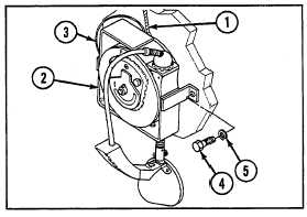
6-31 REPLACE TROUBLELIGHT ASSEMBLY--Continued
a. REMOVAL
1
Disconnect connector (1).
2
Remove troublelight assembly (2) and ground
lead (3) by removing two screws (4) and two
lockwashers (5).
b. INSTALLATION
1
Install troublelight assembly (2) and ground lead
(3) using two screws (4) and two new lockwashers (5).
2
Connect connector (1).
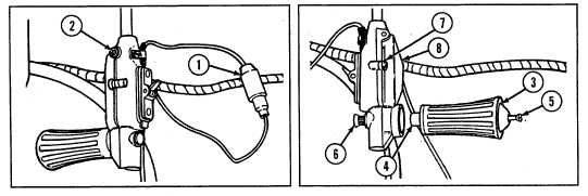
6-32 REPLACE/REPAIR RIGGER'S FIXED SPOTLIGHT AND RELATED PARTS
THIS TASK COVERS
a. Removal
b. Disassembly
c. Assembly
d. Installation
INITIAL SET-UP
Tools:
Tool kit, general mechanic's (Appendix C, item 53)
WARNING
Be certain MASTER switch is OFF when working on electrical system to avoid electrical shock and bums.
a. REMOVAL
1
Disconnect connector (1) and remove socket head screw (2).
2
Remove handle (3) and spacer (4) by loosening screw (5).
3
Remove gear bolt (6) and two screws (7) from body (8).
4 Pull switch assembly (9) off shaft (10).
5 Remove connector shell (11) from wire (12) by removing C-washer (13).
6-68