TM 9--2350--292--20--2
0354 00--9
OUTPUT REDUCTION UNIT (OUTPUT DRIVE) REPLACEMENT --
CONTINUED
0354 00
Installation--Continued
CAUTION
To avoid damage to drive shaft, attach final drive sling to
final drive sling adapter plate and to output drive with
screws normally used to secure track drive hub to output
drive and previously removed as part of the track drive
hub and sprocket removal process.
4. Attach final drive sling (item 37, WP 0717 00) to suitable lifting device. Attach final drive sling adapter plate (21)
to final drive sling with four screws normally used to secure track drive hub to output drive. Raise suitable lifting
device sufficiently to align final drive sling adapter plate (21) to output drive (19). Fasten final drive sling adapter
plate (21) to output drive (19) with four screws normally used to secure track drive hub.
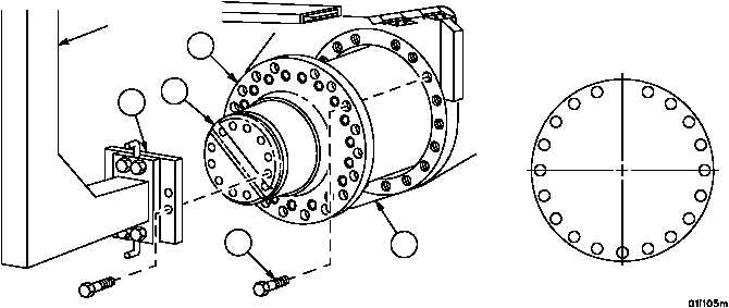
5. Position output drive (19) next to hull opening. Raise output drive sufficiently to get brake apply lever (hidden) to
clear hull opening. Lower drive and align to hull opening. Push output drive into hull until output drive housing
(26) is against hull (23).
6. Install 19 new self--locking screws (22) to secure output drive to hull (23). Torque screws using indicated se-
quence to 200--225 lb--ft (271--305 NSm) (item 9, WP 0717 00).
7. Remove final drive sling and final drive sling adapter plate (21) from output drive and suitable lifting device.
Figure 165
1
2
3
4
5
6
7
8
9
10
11
12
13
14
15
16
17
18
19
TORQUE SEQUENCE
21
22
23
19
26
FINAL
DRIVE
SLING